Engineering Technology, XMUT 2024
Lab 2 “Fun with LEDs”

Due 24 March (
Extended to 31 March ), 19 pm (Xiamen Time)
 Note: You must present your projects to co-teachers or tutors in the lab.
 This is a group lab.
 You can either use a real Arduino or Tinkercad simulator to test your codes.
Resources and links:
To Submit:
-
KnightRider.ino (the arduino sketch)
-
LEDdice.ino (the arduino sketch)
-
DebouncingSwitch.ino (the arduino sketch)
 Make sure your files have these names.
"Knight Rider" effect (Core):
The Knight Rider is one of the nice Arduino projects for beginners. What is Knight Rider? It is a set of LEDs that blinks one after another. So, you are going to make a blinking set of LEDs.

Create a new sketch (
KnightRider.ino) to blink six LEDs one after another and make a "Knight Rider" effect. The required components are as follows:
(First unplug the Arduino)
- A Breadboard
- Six LEDs
- Six resistors (greater than 220Ω)
- wires.
Connect the LEDs and resistors to pins 2, 3, 4, 5, 6, and 7, just like in the video:
A switch can be connected to an Arduino pin to turn an LED on or off.
Switch step 1 (Completion)
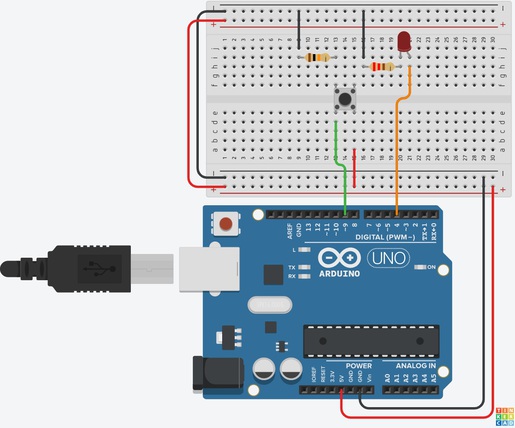
The required components are as follows:
(First unplug the Arduino)
- A Breadboard
- An LED
- A 220Ω resistor
- A 10kΩ resistor
- A pushbutton switch
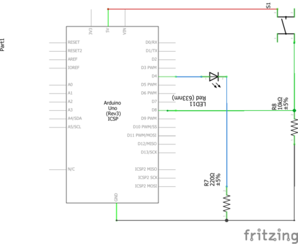
When the switch is closed, the digital pin is connected to 5V and the pin state is HIGH. When the switch is open, the 10kΩ pull-down resistor permits a small current to flow between the digital pin and GND, so the pin state is pulled down to LOW.


The following sketch allows a switch (on pin 8) to turn an LED (on pin 4) on and off.
   const int switchPin = 9;             // define switch pin
   const int LEDpin = 4;                // define LED pin
   int switchPressed = 0;               // define reading as integer
   void setup() {
      pinMode(LEDpin, OUTPUT);          // LED pin as output
      pinMode(switchPin, INPUT);        // Pushbutton Switch pin as input
   }

   void loop() {
      // get the input
      switchPressed = digitalRead(switchPin);
      //change the output
      if (switchPressed == HIGH ) {
         digitalWrite(LEDpin, HIGH);
      }
      else if (switchPressed == LOW ) {
         digitalWrite(LEDpin, LOW);
      }
   }
In the above sketch, the LED is on while the switch is pressed and off while the switch is not pressed.

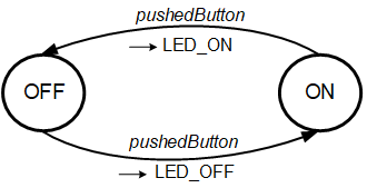
Now change the sketch so that pressing the switch will turn the LED off if it is currently on, and will turn the LED on if is currently off. To do this, the sketch will need to remember the current state of the LED. You can use this FSM to design it.

Switch step 2: Debouncing (Completion)
In the previous sketch, when you press the switch, sometimes the LED does not turn on or off. When a switch is pressed, the springy nature of the metal used in the contact points can cause the contact points to touch several times. This behaviour is called bouncing. The switch can be debounced by using a timer.
There are two software methods for debouncing. One software method introduces a delay using
delay(milliseconds) function, following a change in the switch state. Then it reads the switch state again after the delay.

Change your pushbutton sketch by adding the following code to introduce a delay:
   void loop() {
      switchPressed = digitalRead(switchPin);       // read the signal from switch pin
      if(switchPressed == HIGH){                    // if state of switch has changed
         delay(50);                                 // debounce time of 50ms
         switchPressed = digitalRead(switchPin);    // read the signal from switch pin again
         if(switchPressed == HIGH){                 // compare switch state again
            ...........
            ...........                            // now switch the LED on or off.
         }
      }
   }
Test yourself: Does this program work? What happens if the delay is too short?
LED Dice (Completion)

Create a new sketch (
LEDdice.ino) to show a dice throwing with LEDs. If you press the button, a random number between 1 and 6 is generated, and the corresponding number of LEDs are turned on.
 Hint:
Hint: You can use
random(min, max) function to generate pseudo-random numbers.
min is the lower bound of the random value and
max is the upper bound of the random value, exclusive.
The required components are as follows:
(First unplug the Arduino)
- A Breadboard
- Six LED
- Six 220Ω resistors
- A 10kΩ resistor
- A pushbutton switch
Connect the pushbutton switch, LEDs and resistors to pins 3, 4, 5, 6, 7, 8 and 9, just like in the video:
Debouncing switch with time (Challenge)
The problem with using
delay for debouncing a switch button is that it blocks the Arduino from doing anything else while it is waiting. A better method is to record times.
The second software method is to remember the time when the switch changed, and then keep checking time until the debounce time has passed, then check whether the switch is still in the same state.

Write a sketch (
DebouncingSwitch.ino) that instead of using
delay(milliseconds) function, it uses
millis() function for debouncing. The
millis() function counts the number of milliseconds that the sketch has been running.
 Hint:
Hint: You should use a
unsigned long variable to store the current time.
Note: You must present your projects to co-teachers or tutors in the lab.
This is a group lab.
You can either use a real Arduino or Tinkercad simulator to test your codes.

 The following sketch allows a switch (on pin 8) to turn an LED (on pin 4) on and off.

