Digital Electronics, XMUT 2024
Lab 1: Introduction to microprocessor machine code programming

Due 10 March , 19 pm (Xiamen Time)
 Note: You must present your projects to co-teachers or tutors in the lab.
Resources and links:
To Submit:
 Make sure your files have these names.
Lab Description
During the lab sessions, you will need to save your work in a folder (e.g., ECEN202-lab1) relevant to the lab being undertaken. Download the skeleton code for the current lab (
lab1.hex) file into your newly created folder.
During this first session, the idea is to become acquainted with a microprocessor's fundamentals and how it operates at the machine code level. You will also learn about the development environment you will be using for the next sets of labs where you build circuits and then write, compile, debug, download and run your programs to run on your configured system. The microprocessor you will be using is based on the 8051 series core found in many devices, such as the C8051F020.
Your microprocessor development board is connected to the PC's USB port. Many connectors on the development module will interface to several other devices such as an LCD display and a digital to analog converter.
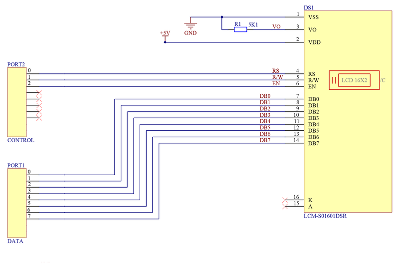
Before a program can be run, it must have suitable hardware to run on. As you will have noticed, the microprocessor development board doesn’t have an LCD display! We will have to connect one to it by using cables and a breadboard. Please build up the following circuit:
Circuit diagram
Lumix LCM-S01601DSR, 16x1 LCD display
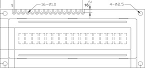
| Pin No. |
Symbol |
External Connection |
Function Description |
| 1 |
VSS |
Power Supply |
Ground |
| 2 |
VDD |
Power Supply |
Supply Voltage for Logic (+5.0V) |
| 3 |
V0 |
Adj. Power Supply |
Supply Voltage for Contrast (approx. 0.5V) |
| 4 |
RS |
MPU |
Register Select signal. RS=0: Command, RS=1: Data |
| 5 |
R/W |
MPU |
Read/Write select signal, R/W=1: Read R/W: =0: Write |
| 6 |
E |
MPU |
Operation Enable signal. Falling edge triggered. |
| 7-10 |
DB0 – DB3 |
MPU |
Four low order bi-directional three-state data bus lines. These four are not used during a 4-bit operation. |
| 11-14 |
DB4 – DB7 |
MPU |
Four high order bi-directional three-state data bus lines. |
| 15 |
NC |
- |
No Connect |
| 16 |
NC |
- |
No Connect |
EX-F02x-Q100 Standard, C8051F Development Board
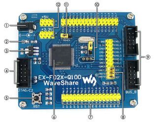
1: 5V DC jack (default power input), 2: Power indicator, 3: Onboard regulator (3.3V, AMS1117-3.3), 4: 10-pin JTAG/C2 port, 5: Reset, 6: Microcontroller (C8051F020, TQFP100 package), 7: Pin headers connected to MCU pins ( marked clearly on the PCB, easy for testing and further expansion), 8: AD/DA voltage reference, 9: BUS-A & BUS-B expansion ports (for connecting to DVK501, header pinout definition is provided, ease to develop various peripherals), 10: External crystal configuration (onboard 16M crystal, custom crystal socket, selected via jumper), 11: VDD monitor enable/disable jumper, 12: Power input/output (5V/3.3V, spare power input, power output is available)
At this stage, it is useful to connect the microcontroller to the PC, as shown below. We need to do this to set up the flash tools. There are two indicator LEDs, one beside the USB and one beside the DC jack. Check that both of them are on before continuing. If
you are having problems, ask the demonstrator.
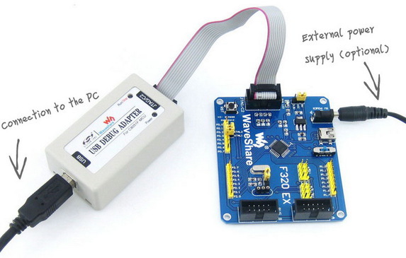
At this stage, it is useful to connect the microcontroller to the PC. We need to do this to install the flash tools. Connect the Microcontroller using a 5V DC power supply and use a USB cable and connect it to the PC. Both the power supply and the USB cable must be connected for the micro to communicate to the PC. Ensure that the UART switch on the box is turned to the ‘on’ position. There are two indicator LEDs, one beside the USB and one beside the DC jack. Check that both of them are on before continuing. If you are having problems, ask the demonstrator.
Installing FLASHUtil Installer
The Flash Programming Utilities is a standalone tool that supports the USB Debug Adapter, C8051 devices. It allows you to download your code to a device and perform other memory operations without using the Silicon Labs IDE.
To run the Flash Programming Utilities, download
FLASHUtil Installer and install it.
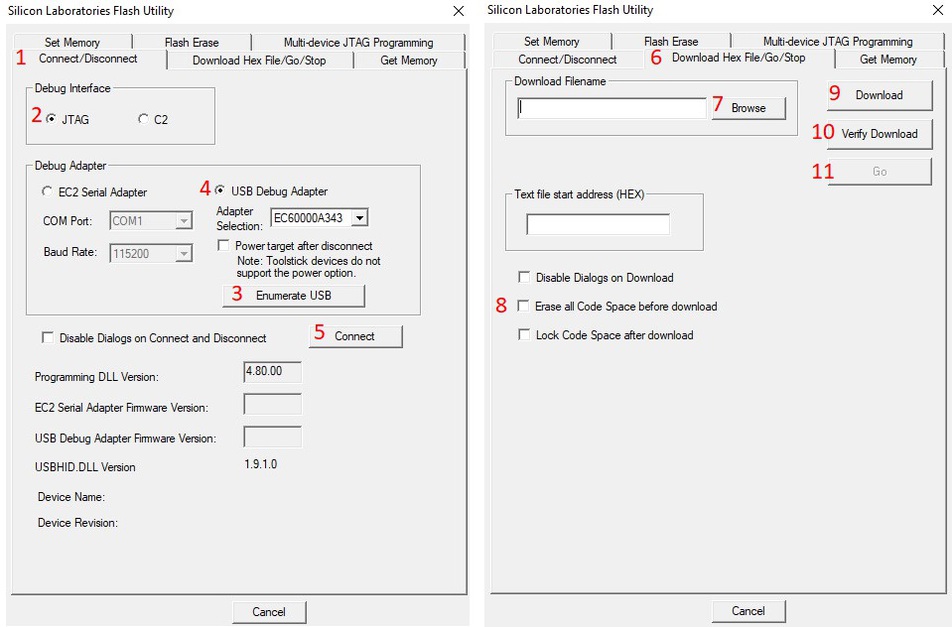
Follow these steps:
- Launch the "Silicon Laboratories Flash Utility” tool.
- Under the Connect/Disconnect tab, select Debug Interface as JTAG.
- In the Debug Adapter, click on Enumerate USB, then select USB Debug Adapter
- Click on the Connect button.
- After the successful connection, go to the Download Hex File/Go/Stop.
- In the Download Filename, find the lab1.hex and open it. This file contains the bitstream (binary file) that will be downloaded to the board.
- The next step is to see the program running, (it is rather useless otherwise!). To do this, we need to download the program to the microprocessor board. Select "Erase all Code Space before download" and then click of Download button.
- Verify Download to see the program is successfully downloaded into the microcontroller.
- Click on the Go button to run the program on the microcontroller.
Verify that the “Hello” message appears on the LCD. (ask the demonstrator if this is not the case).
So, we have now simply "downloaded" a precompiled program onto a microprocessor. Pretty simple stuff so far isn't it? This may seem trivially easy, but it is vital that you get a good feel for the system before you attempt anything too complicated.
Your task now is to decipher the Lab1.hex code and then change it to display your own message. Download the
at_c51ism.pdf and
C8051F02x.pdf files to help you work out what is happening. Don’t Panic!, we will help you through this.
Please include a Mnemonic listing of your code (with suitable comments) in your lab report.
Note: You must present your projects to co-teachers or tutors in the lab.

 1: 5V DC jack (default power input), 2: Power indicator, 3: Onboard regulator (3.3V, AMS1117-3.3), 4: 10-pin JTAG/C2 port, 5: Reset, 6: Microcontroller (C8051F020, TQFP100 package), 7: Pin headers connected to MCU pins ( marked clearly on the PCB, easy for testing and further expansion), 8: AD/DA voltage reference, 9: BUS-A & BUS-B expansion ports (for connecting to DVK501, header pinout definition is provided, ease to develop various peripherals), 10: External crystal configuration (onboard 16M crystal, custom crystal socket, selected via jumper), 11: VDD monitor enable/disable jumper, 12: Power input/output (5V/3.3V, spare power input, power output is available)
 At this stage, it is useful to connect the microcontroller to the PC, as shown below. We need to do this to set up the flash tools. There are two indicator LEDs, one beside the USB and one beside the DC jack. Check that both of them are on before continuing. If
you are having problems, ask the demonstrator.
 At this stage, it is useful to connect the microcontroller to the PC. We need to do this to install the flash tools. Connect the Microcontroller using a 5V DC power supply and use a USB cable and connect it to the PC. Both the power supply and the USB cable must be connected for the micro to communicate to the PC. Ensure that the UART switch on the box is turned to the ‘on’ position. There are two indicator LEDs, one beside the USB and one beside the DC jack. Check that both of them are on before continuing. If you are having problems, ask the demonstrator.
 Verify that the “Hello” message appears on the LCD. (ask the demonstrator if this is not the case).
So, we have now simply "downloaded" a precompiled program onto a microprocessor. Pretty simple stuff so far isn't it? This may seem trivially easy, but it is vital that you get a good feel for the system before you attempt anything too complicated.
Your task now is to decipher the Lab1.hex code and then change it to display your own message. Download the at_c51ism.pdf and C8051F02x.pdf files to help you work out what is happening. Don’t Panic!, we will help you through this.
Please include a Mnemonic listing of your code (with suitable comments) in your lab report.